Configurable Real-Time Multi-Sensing System
09/2025 - 06/2026
Overview
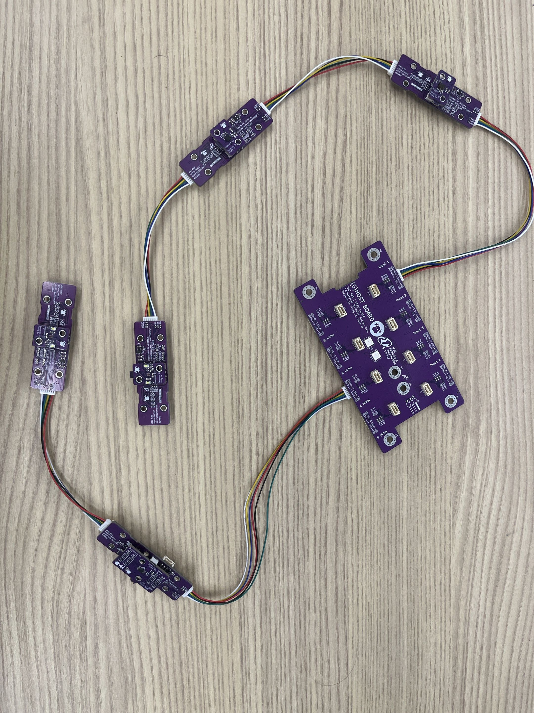
The configurable real-time multi-sensing system is a custom sensor system for UT Austin's VEXU GHOST robotics team with universal multi-sensor integration into robots and dynamic configuration of sensor I2C addressing and real-time data acquisition. The purpose of the system is to enable reliable long-distance sensor communication with the robot's system-on-module, increasing wiring distance and mitigating noise coupling, signal interference, and consequential crosstalk and parasitics from harnessing the longer wires. The system consists of multiple base sensor deployment boards that universally deploy different sensor modules, such as color sensor, distance sensor, and IMU, as well as a sensor hub board that connects all of the deployment boards and performs data acquisition on the sensors with a RTOS firmware. The system utilizes a custom hardware architecture of differential I2C as the primary signal transmission protocol through PCA9615 differential I2C bus buffer, board daisy-chaining to reduce the overall physical I2C bus size, and I2C address manipulation through LTC4316 single-I2C address translator to uniquely interface identical I2C peripherals.
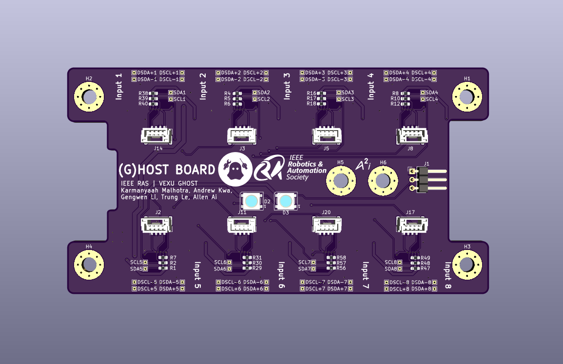
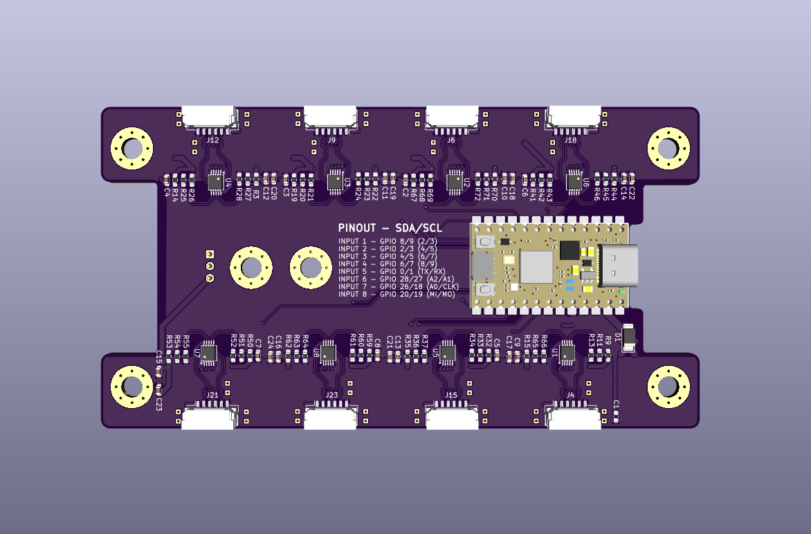
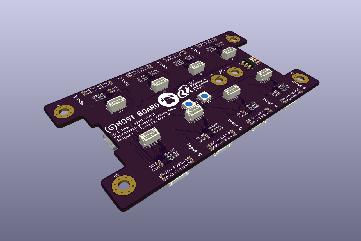
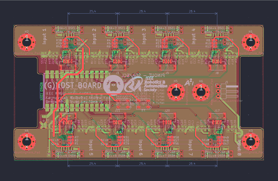
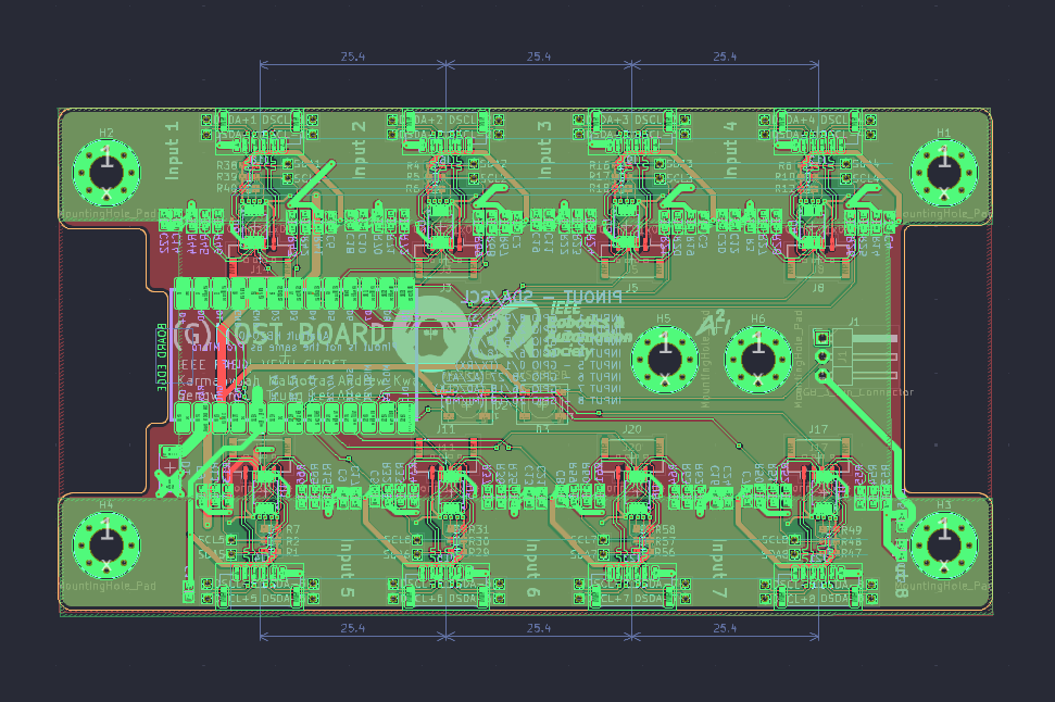
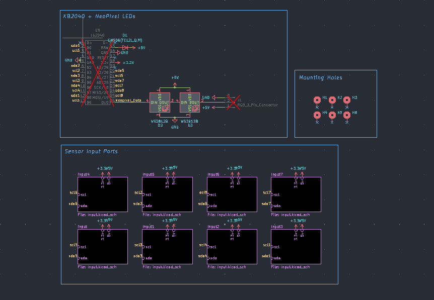
The sensor hub board utilizes an RP2040 and allows for 8 simultaneous I2C bus, 2 hardware I2C bus from the microcontroller and 6 software-programmed I2C bus, meaning theoretically the hub can support the interfacing of more than 400+ I2C sensors. It acts as a communication host, and the Jetson Orin Nano which processes our sensor data to run autonomous operations. I collaborated with other members of the GHOST hardware team to incorporate the differential I2C and daisy-chaining communication architecture into the host board, utilizing PCA9615 for differential pairing and buffering of the I2C buses and an RP2040 to acquire and process the raw sensor data in real-time. The board layout is designed with differential I2C pairs connecting from the docks of the hub to the deployment board using JST GH connectors, single I2C buses to the RP2040 for interfacing, and testing points for easy testing and debugging.
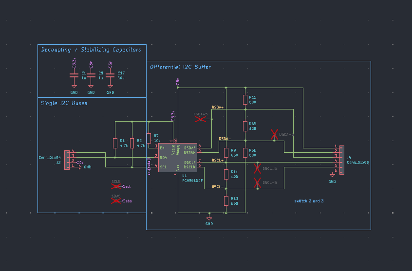
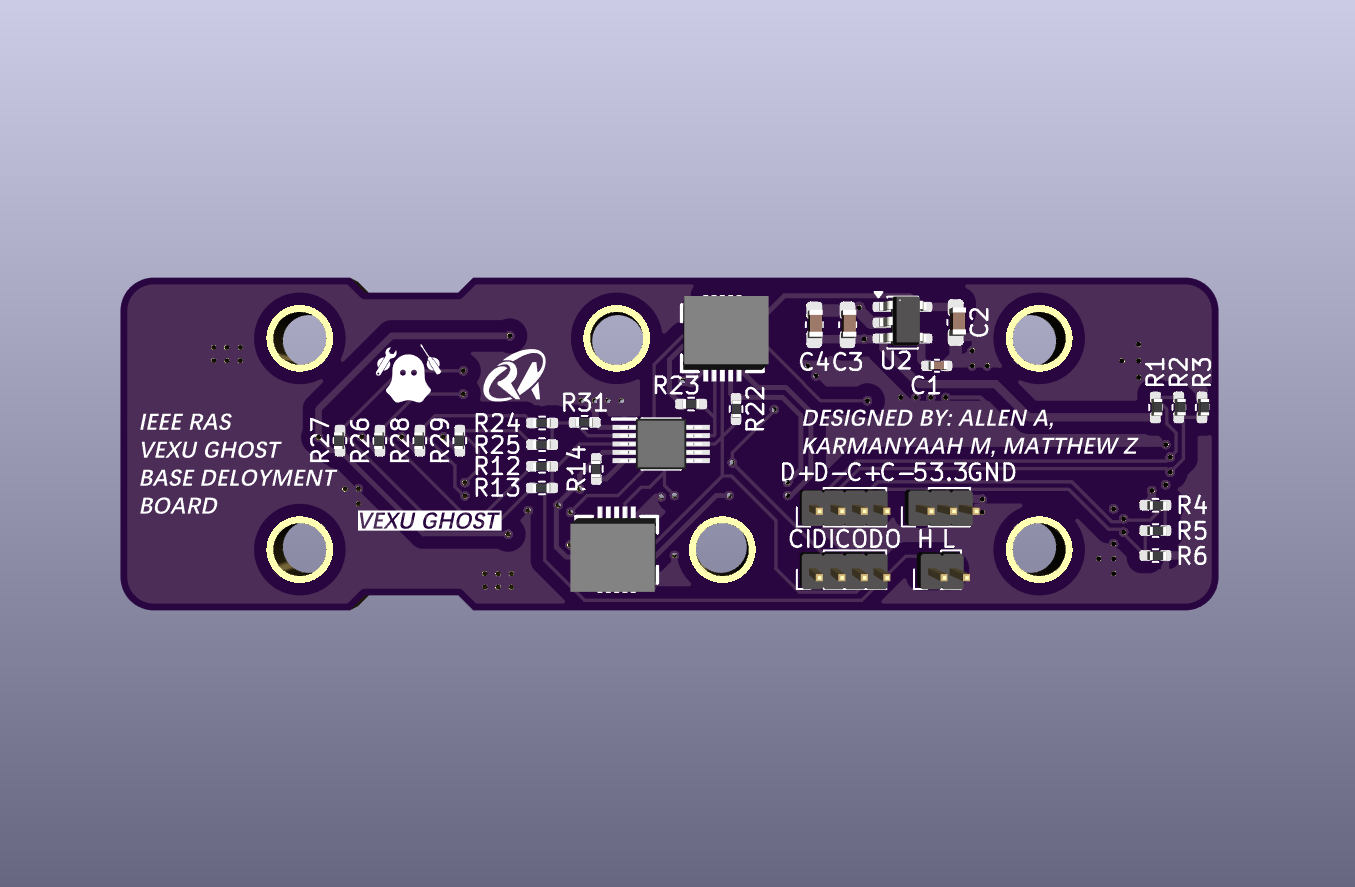
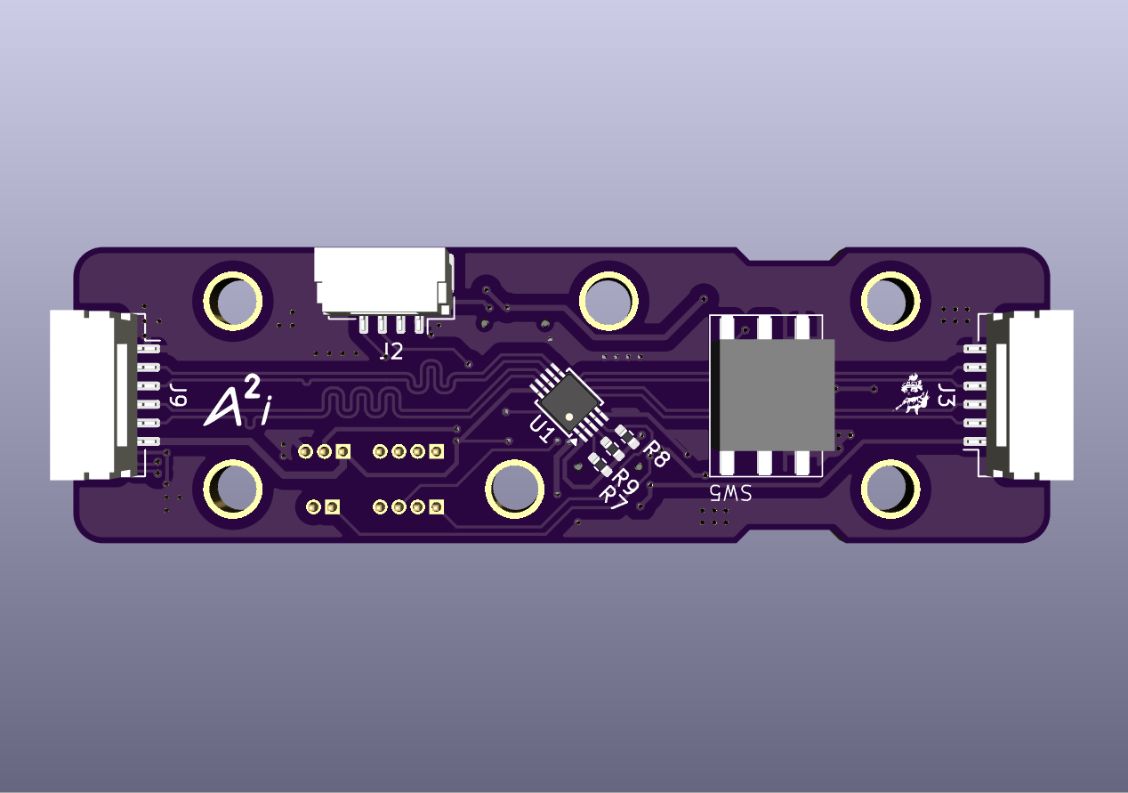
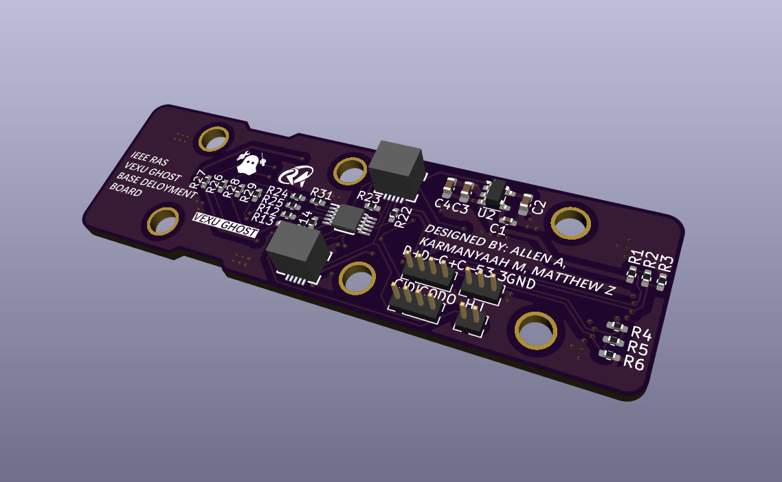
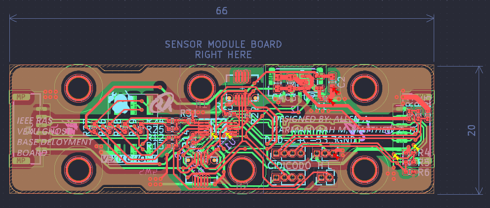
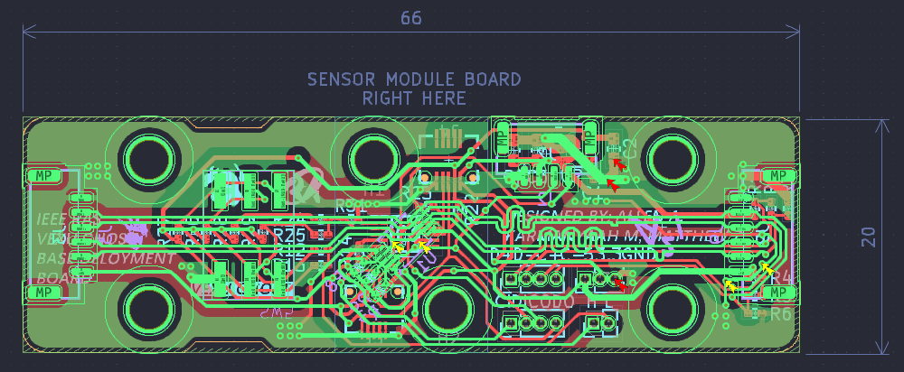
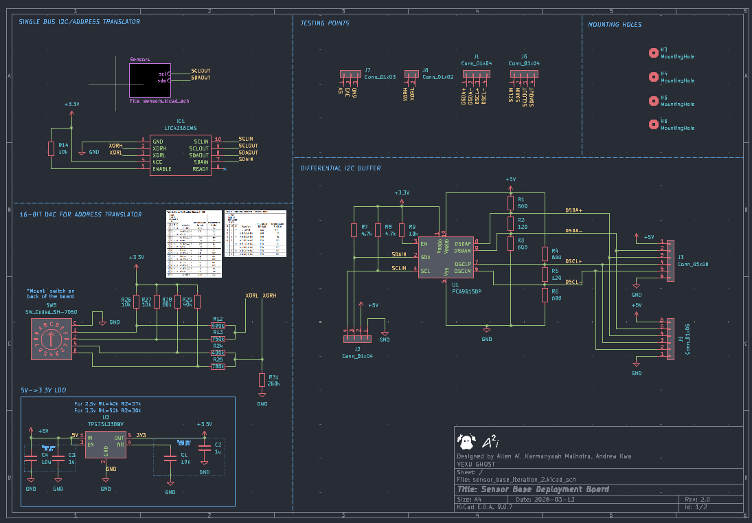
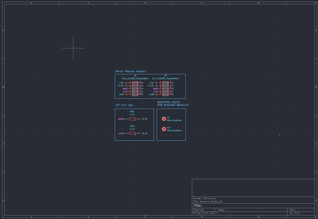
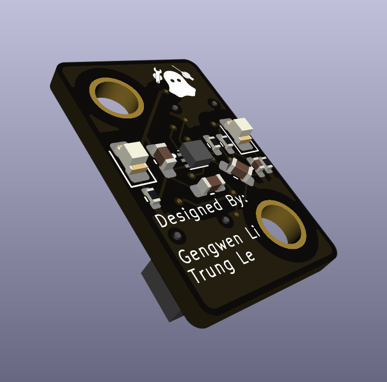
The sensor deployment board also utilize a PCA9615 to buffer the differential pair buses and convert differential I2C signals to single I2C signals for the sensor device, LTC4316 I2C address translator and a 16-bit DAC with a rotary switch to bit-mask the targeted I2C address and creating a unique address in the cases of interfacing identical sensors, and the sensor devices are deployed as smaller module boards by connected to the deployment board through board-to-board connectors universal across all of the modules. The available sensor modules are color sensor (Renasas ISL2914), distance sensor (STM VL53L4CD), IMU (TDK ICM-20602), and (though not a sensor) I2C GPIO expander (TI PCA9536) for limit switching or device driving applications. The deployment boards can be daisy-chained between each other and be connected to the sensor hub as one continuous differential I2C bus, reducing both wiring length and current return path distance.
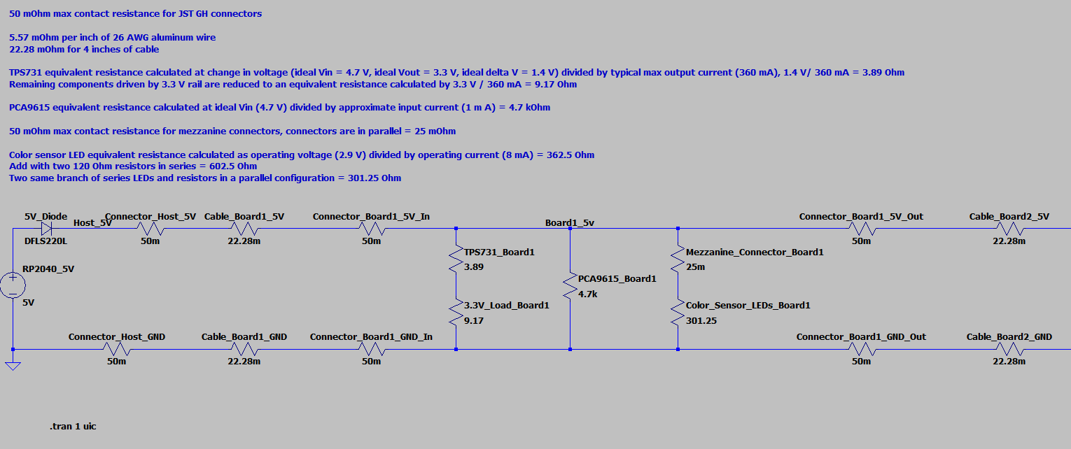
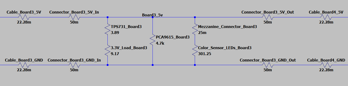
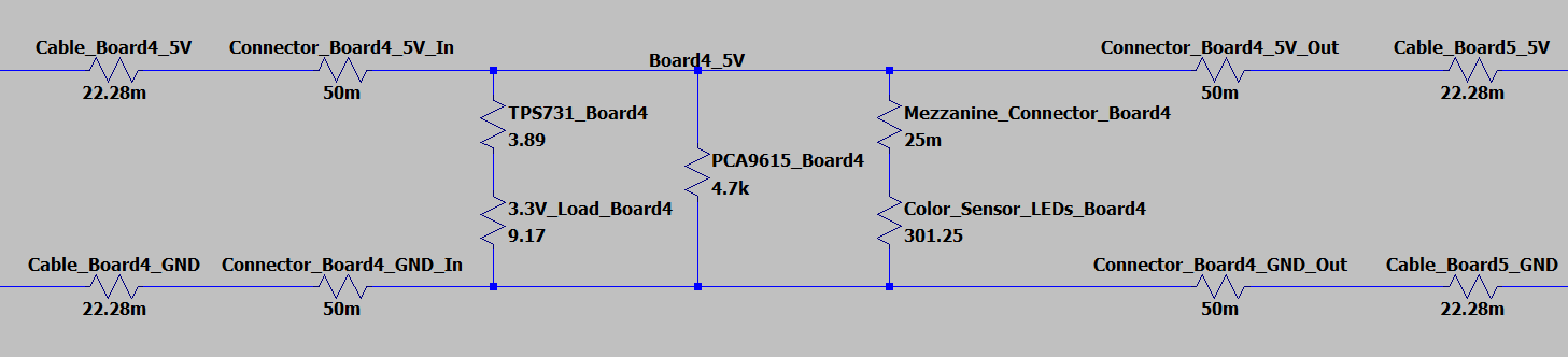
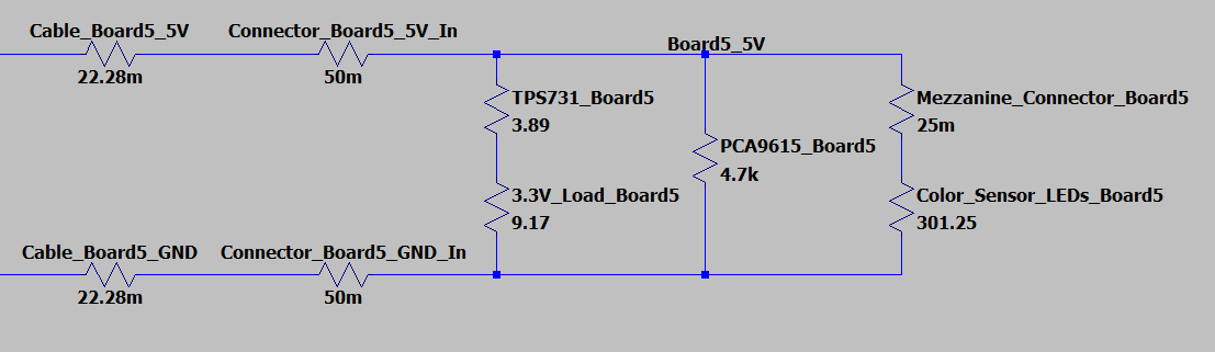
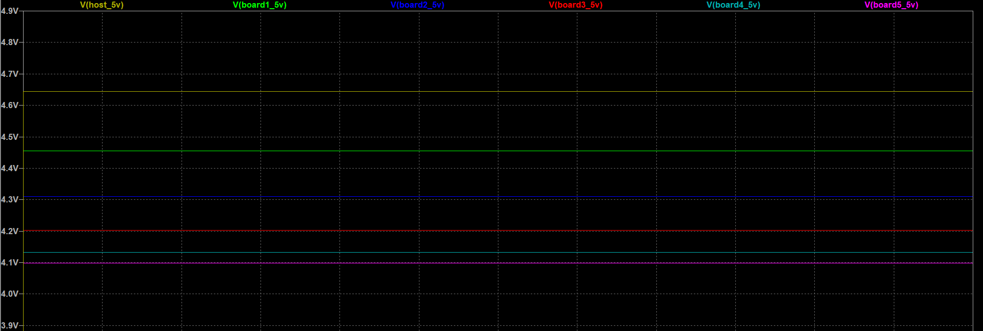
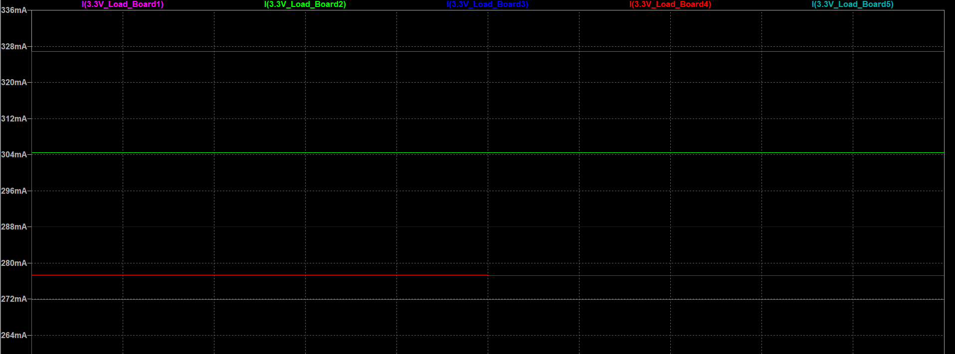
To ensure long-distance functionality, I simulated the system's power distribution simulation in LTspice, replicating a full sensor system with five daisy-chained sensor boards for typical and worst-case test conditions to prevent brownout and ensure limited IR drop and stable operational voltage across the daisy-chained boards.
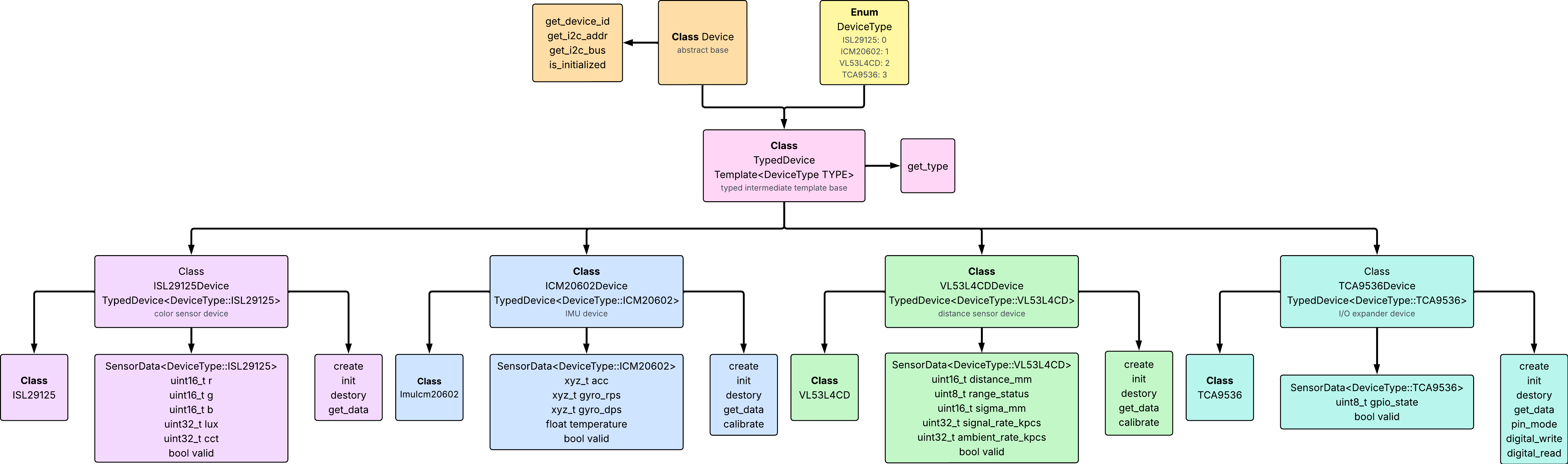
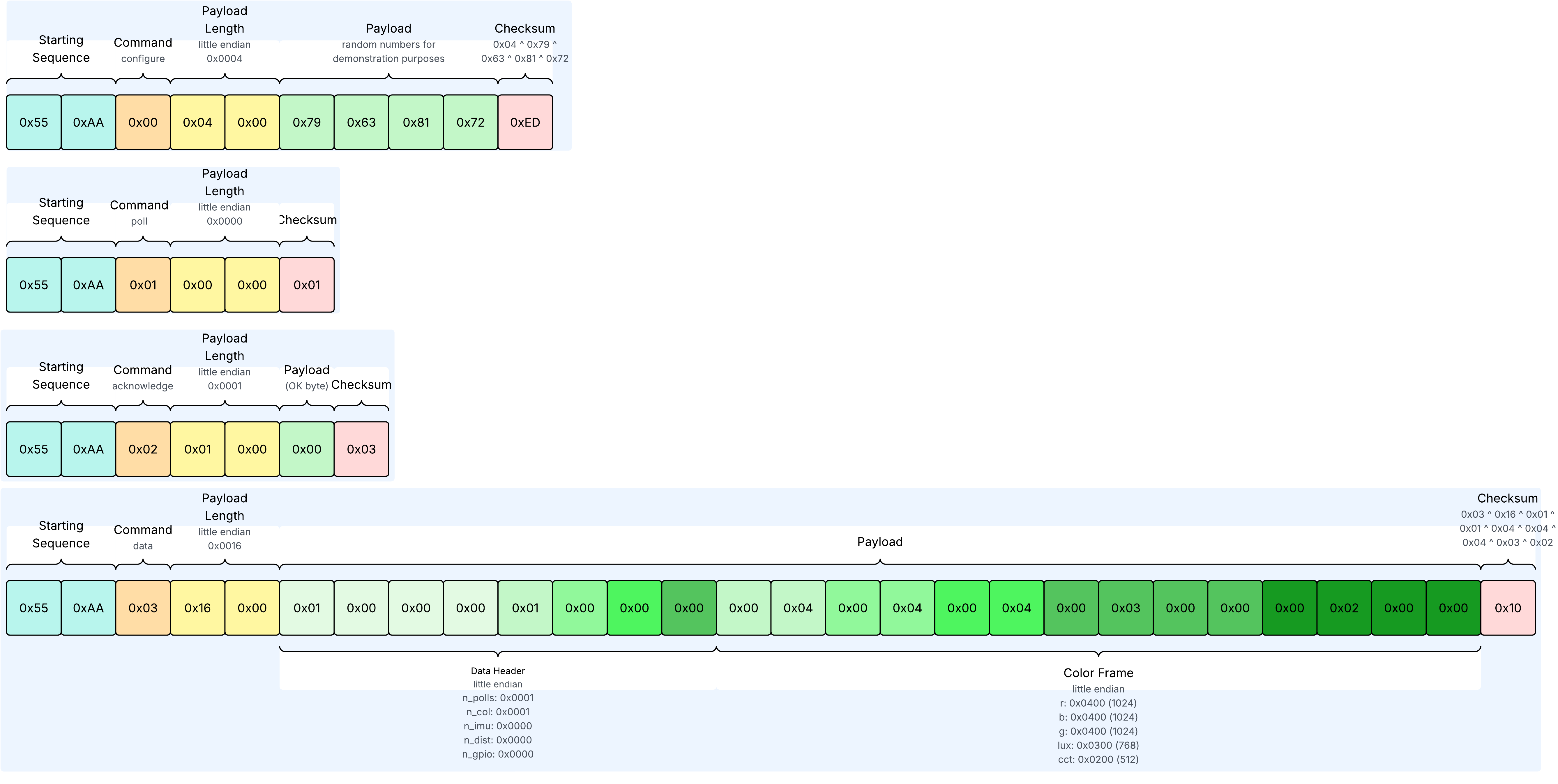
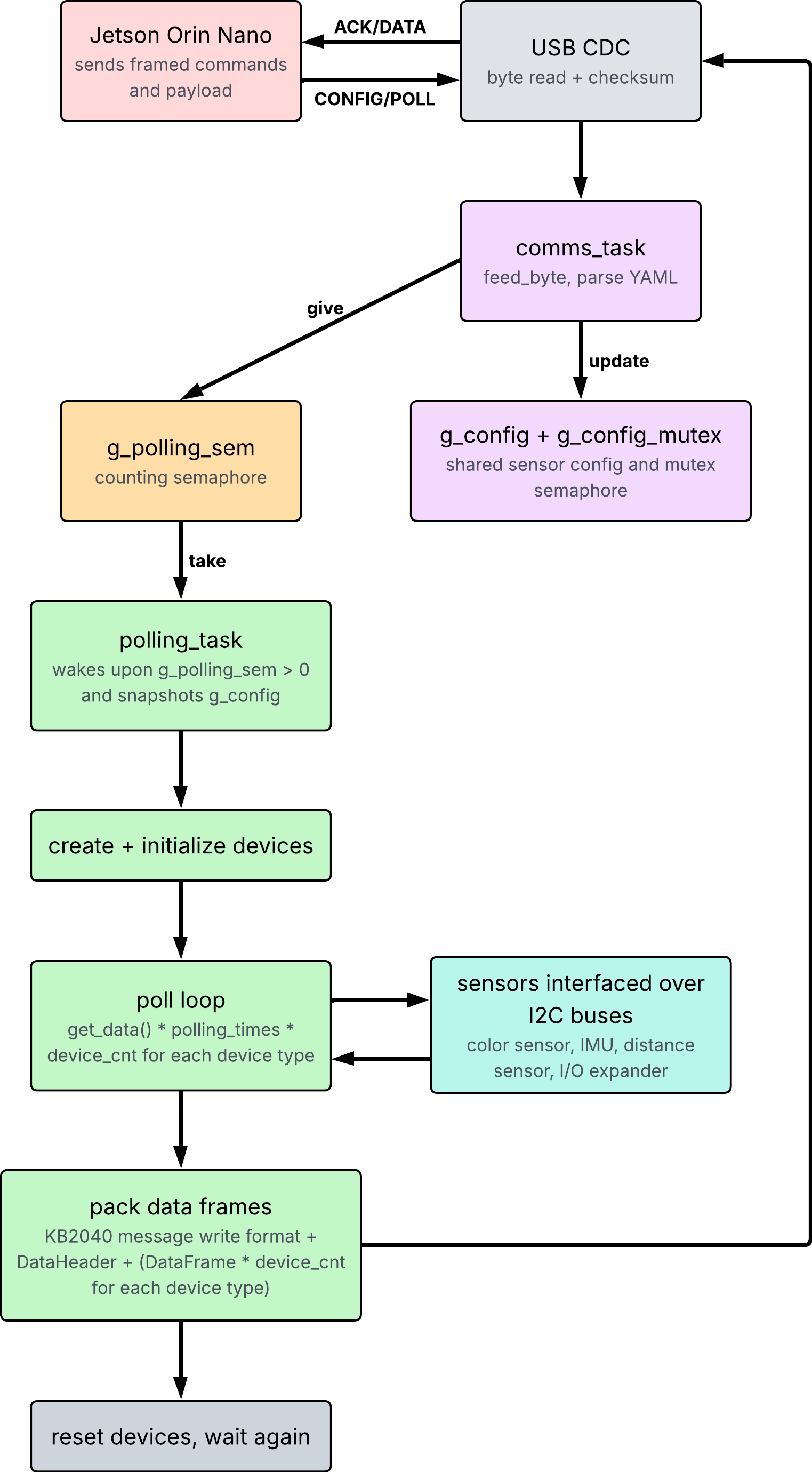
The sensor system operates from a data acquisition firmware written in C++ using Pico SDK, FreeRTOS, and ROS 2. As the RP2040 on the sensor hub board is connected to the robot's main processor and SoM, a Jetson Orin Nano, which executes it's processes and operations using ROS 2 with subscription and publishing networks, the firmware initiates a polling of the interfaced sensors once it receives a subscription polling request from the Orin, such that if data is available from a sensor, it is retrieved, packaged, and sent to the Jetson Orin Nano over USB serial for publishing to subscribers from other autonomous subsystems. By sending a polling request, the user can configure the number of polls, the period between each poll, the number of interfaced sensors, the type of each sensor, and the initialization parameters of specific sensors, and once the specified polling terminates, the RP2040 remains idle until the next polling request is received to improve power efficiency. Custom sensor drivers were written for all of the sensors to be compatible with the Pico SDK, and sensor driver APIs are abstracted through individual sensor device objects, which are implemented through class inheritance and factory constructors to keep object functions, attributes, and interactions universal. The firmware also implements a real-time operating system using FreeRTOS to allow for continuous scheduling of new polling requests while the thread is executing the current polling request and protection of shared resources between different tasks through semaphores.
The sensor system is integrated into the GHOST robot for various autonomous and mechanical functionalities, such as element intake detection, element color indexing, and element position tracking, and has contributed to the team's success in placing as semifinalists in the 2026 VEX AI World Championship. The system has been tested and validated for long-distance communication, signal integrity, and real-time data acquisition, and has proven to be a reliable and efficient solution for multi-sensor integration in robotics applications.
Images